FTDI FT232RL: Bit Bang Mode (Linux) [Part 2]
In the previous post, we covered the installation of FTDI drivers on Ubuntu. This section focuses on controlling GPIO using a Python script.
FTDI has 8 digital pins used for serial connections (RXD, TXD, RTS, CTS, DTR, DSR, DCD, RI) and 5 CBUS pins. Initially, I thought to use the CBUS pins on my module since they were exposed and assumed they were especially designed for GPIO control. However, I was mistaken when I first looked into the FT232RL schematic diagram. Here is a typical one:
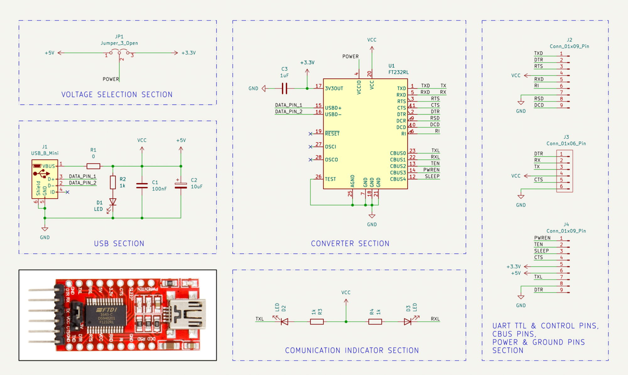
As we can see, CBUS0 and CBUS1 are reserved for the TX and RX LEDs. CBUS2 is used with RS485 receivers, and CBUS3 and CBUS4 have system functions. This behavior can be modified by changing the EEPROM, but it seems complicated since there is no documentation describing the possible EEPROM values. Additionally, the documentation recommends using only the Windows executable FT_PROG.
We will be using RXD, TXD, RTS, CTS, DTR, DSR, DCD, RI as GPIO pins. To summarize the information from the application notes and datasheet for the FT232RL, I have compiled it into a clear table:
UART Pin Configuration
| Signal | Pin No | D2XX Signal |
|---|---|---|
| TXD | PIN_1 | D0 |
| RXD | PIN_5 | D1 |
| RTS | PIN_3 | D2 |
| CTS | PIN_11 | D3 |
| DTR | PIN_2 | D4 |
| DSR | PIN_9 | D5 |
| DCD | PIN_10 | D6 |
| RI | PIN_6 | D7 |
The Python code to make the RXD pin to trigger HIGH for a second and then back to LOW:
import ftd2xx
import time
import sys
from enum import Enum

# Define the PINNames enum with relevant pins
class PINNames(Enum):
    TXD = 0  # PIN_1 | D0
    RXD = 1  # PIN_5 | D1
    RTS = 2  # PIN_3 | D2
    CTS = 3  # PIN_11| D3
    DTR = 4  # PIN_2 | D4
    DSR = 5  # PIN_9 | D5
    DCD = 6  # PIN_10| D6
    RI  = 7  # PIN_6 | D7

class FT232RLDevice:
    def __init__(self, device_index=0):
        try:
            self.dev = ftd2xx.open(device_index)
            print("FT232RL device opened successfully.")
            self.previous_state = 0x00  # Initialize all pins to LOW
            self.dev.setBitMode(0x00, 0x01)  # Set to asynchronous bit-bang mode
            print("Bit mode set to asynchronous bit-bang mode.")
        except ftd2xx.DeviceError as e:
            print(f"Error opening FT232RL device: {e}")
            sys.exit(1)

    def write_pin(self, pin: PINNames, value: bool):
        bit_position = pin.value
        if value:
            self.previous_state |= (1 << bit_position)  # Set the bit
        else:
            self.previous_state &= ~(1 << bit_position)  # Clear the bit
        try:
            self.dev.write(bytes([self.previous_state]))
            print(f"Set {pin.name} to {'HIGH' if value else 'LOW'}.")
        except ftd2xx.DeviceError as e:
            print(f"Failed to write to device: {e}")

    def set_pins_as_output(self, pins):
        bitmask = 0x00
        for pin in pins:
            bitmask |= (1 << pin.value)
        try:
            self.dev.setBitMode(bitmask, 0x01)  # 0x01 for asynchronous bit-bang mode
            print(f"Pins {[pin.name for pin in pins]} set as OUTPUT.")
        except ftd2xx.DeviceError as e:
            print(f"Failed to set bit mode: {e}")
            sys.exit(1)

    def close(self):
        try:
            self.dev.close()
            print("FT232RL device closed.")
        except ftd2xx.DeviceError as e:
            print(f"Failed to close device: {e}")

def toggle_rxd_pin():
    # Instantiate the FT232RL device
    device = FT232RLDevice()

    # Set RXD as output
    device.set_pins_as_output([PINNames.RXD])

    try:
        # Set RXD high
        device.write_pin(PINNames.RXD, True)
        print("RXD is HIGH for 1 second.")

        # Wait for 1 second
        time.sleep(1)

        # Set RXD low
        device.write_pin(PINNames.RXD, False)
        print("RXD is LOW.")
    finally:
        # Ensure the device is closed properly
        device.close()

if __name__ == '__main__':
toggle_rxd_pin()As a result, we see the LED blink for a second. Great! In the video above, I have an optocoupler module hooked to the FT232RL adapter to opto-isolate the controlled pins. I will use it to reset the Sonoff NSPanel Pro 120 into different DFU modes in the upcoming articles. Stay tuned.