Sonoff NSPanel Pro 120: Sound [Part 2]
![Sonoff NSPanel Pro 120: Sound [Part 2]](/content/images/size/w1200/2025/04/Lid_Mech_7.jpg)
This part will focus on getting the capture device to work. In our case, it involves two PDM digital microphones.
PDM MICs
A PDM (Pulse Density Modulation) microphone is a type of digital microphone that converts analog sound waves into a digital signal using a technique called Pulse Density Modulation. In this process, the analog audio signal is represented by a single-bit data stream, where the density of pulses corresponds to the amplitude of the original analog signal.
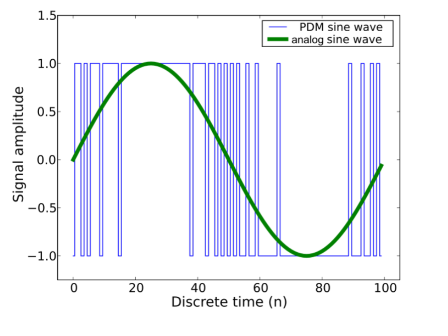
Each PDM microphone has a CLK (clock) pin and a DATA pin. The RK33256 should generate the CLK signal (1–3 MHz) and read the signal from the DATA pin on either the rising or falling edge of the clock. This allows us to connect two microphones (left and right) to a single PDM line. The typical schematic is as follows:
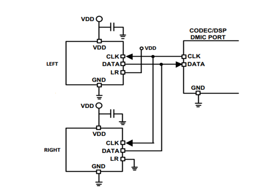
The RK3326 has a PDM peripheral that can handle up to 4 PDM channels (supporting 8 microphones). The lines are labeled SDI0–SDI3 . After explicitly checking the signals on these four lines, I found that SDI1 carries the left and right microphone signals when the clock is applied to CLK1 . Let’s take a look at the .dts configuration:
&pdm {
    status = "okay";
    #sound-dai-cells = <0>;
    compatible = "rockchip,px30-pdm";
    reg = <0x0 0xff0a0000 0x0 0x1000>;
    clocks = <&cru SCLK_PDM>, <&cru HCLK_PDM>;
    clock-names = "pdm_clk", "pdm_hclk";
    dmas = <&dmac 24>;
    dma-names = "rx";
    resets = <&cru SRST_PDM>;
    reset-names = "pdm-m";
    pinctrl-names = "default";
    pinctrl-0 = <&pdm_clk1
                &pdm_sdi1>;
};

rk809_sound: rk809-sound {
    status = "okay";
    compatible = "simple-audio-card";
    simple-audio-card,name = "rk809, pdm-mic-array";
    simple-audio-card,mclk-fs = <256>;
    /*
    Check Part 1 for details on Playback device
    */
    simple-audio-card,dai-link@1 {
        format = "pdm";
        cpu {
            sound-dai = <&pdm>;
        };
        codec {
            sound-dai = <&dummy_codec>;
        };
    };
};

dummy_codec: dummy-codec {
    status = "okay";
    compatible = "rockchip,dummy-dai";
    #sound-dai-cells = <0>;
};
Here, I want to clarify that since we don’t have an external codec and the PDM audio is decoded within the SoC (RK3226) itself, we should use a dummy codec . To enable it, we need to activate the corresponding kernel configuration by adding the following line to the kernel config:
CONFIG_SND_SOC_ROCKCHIP_DUMMY_DAI=yGreat! Let's compile and upload the firmware, then check the microphones' functionality.

We can see that the first capture device is an RK809 mic (even though it’s not connected and not used, I didn’t find a way to disable this capture device). The second card is explicitly what we are looking for. It also turned out that since the microphones are connected to SDI1 , the audio recorded from this card will always have the mic channels mapped to channels 2 and 3 in the resulting .wav file. This makes sense because SDI0 is associated with the RK809 and is essentially unused.
The workaround for this is to create a virtual device in the .asoundrc file that will redirect the logical channels: channel 2 → channel 0 and channel 3 → channel 1.
pcm.main_mic {
    type plug
    slave.pcm "hw:0,1"
    slave.channels 4
    ttable.0.2 1   # Map hardware channel 2 to logical channel 0
    ttable.1.3 1   # Map hardware channel 3 to logical channel 1
}
Great! Let's configure the mic path and the gain levels. Also, since the mic has a noticeable "pop" at the beginning of recording, let's change the PDM delay from 20 ms to 300 ms . At the end, we will start recording using both the left and right channels for a 10-second duration
amixer -c 0 set 'ADC PGA Gain' 15
amixer -c 0 set 'MIC Boost Gain' 3
amixer -c 0 set 'Capture MIC Path' 'Main Mic'
amixer -c 0 cset numid=19 300
amixer -c 0 cset numid=20 300
arecord -D main_mic -f S16_LE -c 2 -r 48000 -d 10 /root/capture.wavThanks, everyone, for your attention! I’d like to conclude that this is the point where we’ve successfully gotten the most significant hardware components to work in Linux. We’ve come a long way and so far have managed to get the display, touchscreen, GPU, Wi-Fi/BT, speakers, and mics working. The remaining tasks involve the light and presence sensors, as well as the Zigbee module. I’ll try to get these working as well.
Additionally, as soon as all peripherals are added to the Buildroot Linux, I’ll switch to Debian and create a stable firmware release for the panel. The next goal will be to compile Android 12 firmware for the panel. Stay tuned—it’s going to be interesting!


